Display and Serial Interfacing of automatic car parking project
4.3 Seven Segment Display
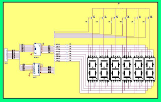
This hardware is used to display the number of cars in the parking lot. Basically, this board has six-segment display but using only one display can do our work. It used segment driver IC SN7447AN and 3*8 decoder to select the corresponding display.
The figure shows the circuit diagram of the seven-segment board. Microcontroller Port2 is use to handle the display unit.
multiplexed Seven segment display board circuit diagram for microcontroller 8051.
4.4 Serial Interfacing
This unit is to display the number of cars in parking lot on the computer. The computer may be placed in any control room. Serial cable is used in null modem mode.
We use the DB9 connector for serial interfacing. In null modem mode pin 7,8 and pin 6,4 are shorted with each other. While pin 3 is used for transmit data and pin 2 for reception.
Rs232 Serial Cable Details for microcontroller 8051 interfacing with computer.
Computer and the micro-controller are connected to each other by serial port through ICL232 (IC 1), the only purpose of which is to convert the voltage levels to the compatible values.
ICL232 needs to be used because the TTL and RS-232 voltage levels are different. In TTL, +5V and 0V are considered as high and low respectively, whereas for RS-232 these are –3V and +3V.
Serial Interface circuit diagram.
BACK to Content Page
Next Page
Previous Page


0 comments: